PROFESSIONAL RESTORATION CLASS
Submitted by Charles Perry Restorations Ltd,
Praewood Farm, Hemel Hempstead Road, St Albans AL3 6AA
The Project
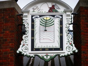
In 2010, Charles Perry Ltd was contacted to remove, restore and replace the elaborate vertical sundial at All Saints’ Church in Isleworth. The Church dates in part, back to 1398. The first sundial there is believed to have been a painted vertical wooden sundial which was dedicated to the memory of Susannah, fourth wife of Colonel Sir Nicholas Lawes (Chief Justice of Jamaica from 1698 to 1703 and Governor from 1718 to 1722) who had died in 1707 at the age of 47. Church records, such as they are, show that the sundial has been repainted and maintained ever since.
Sadly, the church, except for the tower, was destroyed in 1943 by two boys, who had set fire to five churches in the area in the course of a few days, destroying much of the fabric of All Saints’ and one other. After years of indecision the desire for a full restoration was finally abandoned on cost grounds and in 1970 a smaller modern brick building was openly linked to the remaining tower. It is this building that continues in use today and the then present sundial was mounted high (arguably somewhat too high) on the new Lady Chapel of this building.
Deterioration and Decline
By 2010 the sundial had fallen into serious decline. The gnomon was almost completely detached and the dial had become a danger to the public as well as badly deteriorated. A ‘Faculty Jurisdiction’ was therefore duly applied for from the Consistory Court of the Diocese. In view of the length of this procedure, this was done prior to any detailed discussions over the manner of restoration. As a consequence all subsequent restoration works were required to follow the existing physical design, the dial to be replaced in the same place and to use similar materials. Longer life options using more modern materials were not permitted. The very heavy dial was therefore removed from the Lady Chapel tower and transported to our workshop and a sundial consultant appointed to advise upon the scientific aspects of layout and design.
Examination
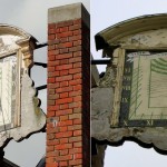
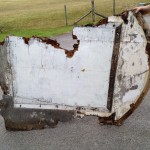
On examination the gnomon was found to be bent and its fixing was broken. The 2½ inch thick plywood backing `for the dial was rotten and incapable of being reused, the easternmost mahogany corbel was partly rotten, the westernmost corbel was missing and the lower part of the dialplate’s framing had become detached. The fixings of the dial to the Lady Chapel were weak and in need of replacement.
There were also many serious errors of dial layout and delineation. Although clearly a declining dial, the hour lines did not meet at the gnomon root, the times given in the place name arcs and the direction stated for Jamaica were all incorrect, the solar altitude scale and the gnomon itself were wrongly centred on the noon line, the altitude lines were drawn as circular arcs and only one declination line (that for the summer solstice) had been drawn but even that had not been identified. Additionally an examination of the gnomon showed that it was badly bent and there didn’t ever appear to have been a nodus whose shadow against the altitude and declination scales would have been needed. The inter-hour markings (which had been painted freehand and again did not point to the dial origin) had been drawn to show intervals of six minutes – something which is thought to be present on no other similar dial in the UK and which, from the Church’s available archival evidence, had never been used on any earlier manifestations of this dial either. It also proved remarkably difficult to measure the original declination of the dial.
The Restoration
Dial Backing
The original dial as removed had been constructed from a single backing piece of 2½ inch thick ply. Its weight had proved to be a major obstacle during its removal from the tower and it was decided that the replacement should be made in two lap jointed halves of Lloyds Register marine ply that could be simply bolted together after raising them in place. This was achieved using concealed fittings. The reduced sizes of the component parts also made it easier for the dial to be transported.
After removal of the sundial from its elevated position, the full extent of decay to the main panel could be seen. The original construction would have been in solid timber.
Over the sundial’s existence, various levels of repair and replacement have been carried out. After close inspection of the structure, it could be seen that the main panel section was non-weatherproof plywood, the dial was also plywood and the applied mouldings, top arch sections and corbels were mahogany and most likely original elements.
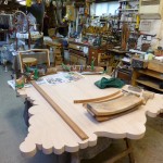
Original elements were retained where feasible. Some of these elements required new timber splicing in and shaping in. A previously replaced section of the curved cornice moulding was replaced in mahogany as the original. One corbel also had new mahogany spliced in to the original. The remaining corbel that had been extensively and poorly repaired was completely replaced in mahogany and carved as the original.
The first stage of creating the main panel was to make a full size mock-up/template. The template also allowed for a rough sketch of the decoration to be applied. The original back panel is likely to have been approximately 50mm thick. A decision was taken to construct the new main panel in Lloyds Register hardwood marine ply. Taking into account the size and weight of the panel, a construction method was used to reduce the weight and overall size. To achieve this, the tower part of the panel was made in 25mm ply with an additional, wide, 25mm thick frame section on the reverse side. This gives the appearance of the whole panel being 50mm thick. The top arch was made as a separate section with a large lap joint fixed with stainless steel screws to join the two sections together. A replacement dial plate was also made in marine ply.
Gnomon
The original damaged brass gnomon was straightened and positioned correctly
Nodus
A new nodus was manufactured and positioned according to the dialplate design
Declination re-estimated
This was confirmed using several alternative approaches and from the angle of the straightened gnomon.
Delineation and time lines
All aspects of dial layout were confirmed by the use of a computer program using conventional time intervals
Loxodromic Bearings
These are ship’s bearings which if followed continuously would lead to the place in question. These loxodromic or rhumb lines cross all meridians in their path at the same angle. They are represented by straight lines on a Mercator projection and the directions given on the Isleworth dial were checked using Colton’s 1855 Map of the World. On the 1999 dial the directions stated for Jerusalem and Moscow were correct but that for Jamaica was wrongly given as “S.W”. rather than as the correct “S.W. by W”.
Layout
The key aspects of the dial layout were then developed using computer aided design and the whole printed full size as a ‘cartoon’ onto drawing paper which was then laid on a board.
Testing
A custom designed jig was manufactured to hold this paper version and the board so as to simulate the correct positioning of the dial in Isleworth when the sun shone in St Albans. All aspects of the design were found to be correct.
Artwork
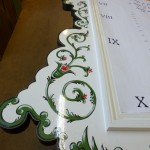
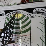
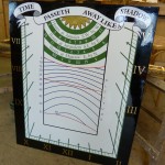
The artwork styles for the arched pediment, motto, numerals and directional arcs were then decided by reference to what earlier information was to be found in the Church Archives.
Time Pressures
At this point in the restoration the Church requested that the work be completed in time for their planned summer fete. This presented the team with considerable additional difficulty.
Painting
The dial plate was painted white using a three part system ready to take the final artwork. The design on the CAD drawing was then pricked through onto the dialplate ready for painting.
The colours for the various aspects of the design were decided in accordance with Church Archive images that still existed where the colours could be estimated.
Dial protection
Once the painting had been completed the scalloped edges of the backing together with the tops and horizontal inner surfaces of the pediment were covered in lead and the gnomon, together with its new spherical nodus was fitted.
Installation
Following this the dial was transported, assembled and installed at All Saints’. Installation to a precise alignment at such a height and with four separate mountings each with three degrees of freedom and against the time pressures indicated above proved difficult. It was aligned as far as was possible given available sunshine. This was done against a pre-calculated table of the solar times that should be indicated at this location for any clock time during the day.
The dial has been well received by the Church authorities.
